|
|
||||||||||||||||||||||||||||||||||||||||
|
|||||||||||||||||||||||||||||||||||||||||
|
The main
objective of this task was to verify the composition and quality of the available
datasets and the validity of the manual annotations therein. Careful analysis
of the facial surfaces revealed an important presence of artifacts which,
additionally, showed a strong dependency of the technology of the device used
for surface acquisition. Given that one of the main objectives of this
project is to obtain tools for highly automated analysis, we decided to avoid
any manual pre-processing of the data, which was kept in its original form. The impact of
artifacts in the input surfaces is task-dependant. On one hand, the automatic
identification of landmarks should be robust to these artifacts as it
constitutes the input block to the system and is aimed at allowing geometric
normalization into a common reference that facilitates further analysis. In
contrast, at the analysis step we aim at working with high-quality and
artifact-free data. While we
successfully constructed a robust automatic landmarking algorithm, it was
concluded that it would be highly desirable to introduce additional processing
blocks to eliminate some of the artifacts present in the input data, such as
singularities, non-manifold geometry, disconnected parts and holes. Hence, we
have implemented solutions that can handle the majority of these issues and
continue investigating some of these aspects in a collaborative setting. |
||||||||||||||||||||||||||||||||||||||||
|
Available data |
||||||||||||||||||||||||||||||||||||||||
|
The clinical
databases that were targeted in this project were acquired with two different
technologies: stereo photogrammetry and hand-held laser scanning. Stereo
photogrammetry produces surfaces with relatively uniform triangulation where
holes and artifacts are not very frequent, except in very specific regions.
For example, it is possible to find surface artifacts near the symmetry line
of the face (due to the need to merge the information captured by the stereo
sensors for each side of the face) and flash reflections can cause
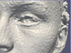
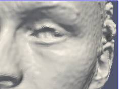
considerable distortion in the eye region. However, the main problem in the
surfaces reconstructed with this technology is the level of noise, which is
especially visible in areas with low curvature and texture contrast (see Fig.
1). This noise puts a question mark on the accuracy of the surfaces that are
reconstructed. So far, we have dealt with this problem by means of a small
smoothing filter, consisting in a bi-quadric approximation of each vertex
using a neighborhood of 3mm around it. This has proven satisfactory for the
task of automatic landmarking. For the analysis step we expect to introduce
methods based on spectral mesh processing to contribute reducing this
problem.
The majority
of data available within this project has been acquired by means of hand-held
laser scanners. This technology produces considerably less noise and is
deemed to provide a more accurate representation of the underlying surface.
The price to pay is a surface triangulation that is not as regular as the one
generated by stereo photogrammetry and the usual appearance of holes and
small surface artifacts. The irregularity in the triangulation has not been
an important issue so far, as it can be dealt with by methods that take into
account the sampling density [Frome 2004]. On the other hand, artifacts and holes do
constitute a problem and we have therefore addressed them, as described
below. Examples of
facial surfaces obtained with hand-held laser scanners are displayed in Fig.
3. A demonstration video showing the acquisition process, followed by our automatic
landmarking algorithm, is provided here. |
||||||||||||||||||||||||||||||||||||||||
|
Cleaning surface artifacts |
||||||||||||||||||||||||||||||||||||||||
|
The In this
project we have focused in surface representations based on vertices and
triangles, arranged in such a way that the result is the discretization of a
two-dimensional manifold embedded in 3D. Violations to this assumption are
considered artifacts and, therefore, they must be fixed before the mesh can
be processed [Gueziec 1998]. ·
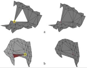
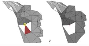
Singular
vertices: in a manifold surface, all vertices must be regular. If we denote
the star of vertex v to all
triangles that share v, then
vertex v is regular if the triangles
in its star cover a span a continuous angular interval and do not present
overlaps. Otherwise the vertex is singular. Some examples of singular
vertices and the solutions implemented to correct those specific artifacts
are provided in Fig. 2 ·
Non-manifold
edges: in a manifold surface, an edge typically belongs to two triangles. If
it belongs to just one triangle is a boundary edge. But if it belongs to more
than two triangles it is a non-manifold edge and, therefore, we need to
modify it. This is done by removing one of the incident triangles, which is
chosen making sure that its removal does not generate new non-manifold edges
or singular vertices. ·
Other
simple artifacts include the presence of degenerated triangles and
disconnected regions, which can be easily removed.
Let us
emphasize that the correction algorithm that has been implemented is fully
automatic. It should also be noted that several tools for pre-processing
triangulated surfaces are available from the research community, but in
general we have found that those tools tend to use rather aggressive
strategies that can considerably modify the surface in the neighborhood of
the artifacted edges or vertices. Hence, we have
chosen to address our own implementation aiming at minimizing the
modifications introduced into the original mesh. |
||||||||||||||||||||||||||||||||||||||||
|
Hole filling |
||||||||||||||||||||||||||||||||||||||||
|
Hand-held
laser scanners capture 3D information by projecting a line of laser light
into the surface of interest and capturing the reflection with a camera.
Since the laser source and the camera are at a fixed relative position, the
depth information can be resolved by triangulation. This simple process
allows a very accurate reconstruction of the surface but it often generates
holes, mainly for two reasons: i) poor reflection
of the laser light in certain types of surfaces like hair (e.g. beard,
moustache, eyebrows), ii) inconveniently curved surfaces that reflect the
light into angles that cannot be covered by the camera (e.g. ears, neck right
behind the chin). Fig. 3 shows examples of surfaces captured with hand-held
laser scanners.
After careful
inspection of the available data, we concluded that a hole-filling algorithm
would be highly beneficial. It is important to emphasize that this solution
was judged as significantly better than the alternative of using
general-purpose tools already available in the scientific community, given
that: i) they are often not fully documented and it
is not completely clear what is actually done (which implies a risk of
distorting the original data beyond needed), ii) almost all hole-filling
algorithms have focused on generating visually pleasant results, without
providing quantitative figures indicating how faithful are the generated
patches (with respect to the hypothetical hole-less surface). Currently,
this line is focused on the evaluation of existing state-of-the-art
hole-filling algorithms and the development of a framework for a quantitative
evaluation, in the terms explained above. We selected 6 hole-filling
algorithms: 3 that work at a global level (the whole surface at once) and 3
that work at a local level (processing one hole at a time). Two of the
algorithms were re-implemented while the rest were run from tools that are
publicly available. Our goal is to measure quantitatively the difference
between the solutions generated by the different algorithms and the original
meshes. This is made feasible by a strategy of hole
mapping, where real holes from one captured surface are mapped onto another
surface that has been captured in the same way, but is free of holes in the
region of interest. As a result, we generated
a realistic dataset of synthetic patches that was also made publicly available
to serve as benchmark material: the CIPA 3D Hole
Patch database. Our results
show that the performance of all methods is similar at a local level, with
small differences due to the simplicity of the approach or the sensitivity to
the parameters. At the global level, the large differences are the result of
the amount of variation the original model suffers. Those algorithms that
produce closed object models are seen as more disruptive for the types of
models used, but at the same time by changing the triangulation and sampling
density, they do introduce significant changes in the original data. Further
details are provided in the following publication: |
||||||||||||||||||||||||||||||||||||||||
|
|
M. Rojas, F.M. Sukno,
J.L. Waddington and P.F. Whelan; “Quantitative Comparison of Hole Filling
Methods for 3D Object Search.” Proc. Eurographics Workshop on 3D Object Retrieval, Strasbourg, France, in press, 2014. |
|
|||||||||||||||||||||||||||||||||||||||
|
|||||||||||||||||||||||||||||||||||||||||
|
References |
||||||||||||||||||||||||||||||||||||||||
|
[Frome 2004] A. Frome, D. Huber, R., Kolluri
et al. (2004). Recognizing
objects in range data using regional point descriptors. In Proc.
European Conference on Computer Vision, pages 224–237, 2004. [Gueziec 1998] A. Gueziec, G. Taubin, F. Lazarus et al. (1998). Converting
Sets of Polygons to Manifold Surfaces by Cutting and Stitching. Proc.
IEEE Conf. on Visualization, pp. 383-390, 1998. |
||||||||||||||||||||||||||||||||||||||||
|
|
||||||||||||||||||||||||||||||||||||||||
|
|
|
|
|
|||||||||||||||||||||||||||||||||||||